Figure 1: F-22 Raptor
Our engineering and manufacturing people assisted in the development of Liquid Flow Through (LFT) for the Air Force’s F-22 Fighter Aircraft. These LFTs were used in the aircraft’s Common Integrated Processor (CIP). Printed Wiring Boards (PWB) were laminated to Liquid Flow Through (LFT) heat exchangers creating Line Replaceable Modules (LRMs). The LFT heat exchangers were the component our people assisted in developing.
From the beginning of the program, the Air Force had enforced stringent integrity requirements through their Avionics Integrity Program (AVIP). They were similar to the design practices followed with Advanced Design for Quality Avionic Systems (ADQAS). The area of greatest concern, from an integrity point of view, was the durability of the solder joints after low-cycle fatigue from thermal cycling. The ceramic packages on the PWB’s have a coefficient of thermal expansion of 6 ppm/ºC, considerably less than the 21 ppm/ºC for the PWB on an aluminum heat exchanger. Although compliant gull-wing leads were used, the mismatch in the CTEs of the package and the PWB were shown to be enough to cause failures in the solder joint. By using a heat exchanger with a low CTE, the effective CTE of the PWB could be reduced enough to ensure the solder joints would survive the thermal environment. This required replacing the traditional aluminum heat exchangers with aluminum-beryllium heat exchangers.
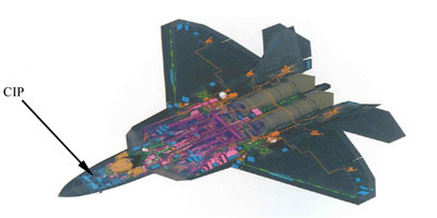
Figure 2: Internal View of F-22 System’s (Avionics in Blue)
Material Properties
Aluminum-Beryllium (Al-Be) is an aluminum alloy developed in the 1960’s under the trade name “Lockalloy” and used on the SR-71. The alloy combines the most favorable components of both aluminum and beryllium (Al-Be) into a single metal. The alloy is made using powder metallurgy techniques. Al-Be has over twice the stiffness as aluminum, yet is 23% lighter. It is just as stiff as some ceramics and yet is almost as machinable as aluminum. The CTE for AL-Be is 14 ppm/ºC, versus 23 ppm/°C for aluminum. Al-Be also offers an increase in thermal conductivity.
Al-Be machines like magnesium and requires the dust to be captured. The chips can be recycled and it does not require post machine etching like pure beryllium. Al-Be joins like aluminum. It can be electron beam welded, brazed or bonded. It is finished like aluminum and can be alodined, painted or nickel-plated.
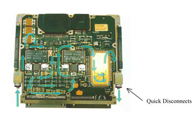
Figure 3: Populated LFT Module
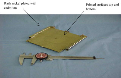
Figure 4: LFT Module
A major concern with choosing Al-Be for a brazed assembly was whether the material had all the processes fully developed and in place. The machining characteristics of Al-Be were fairly well understood, and nickel and other plating samples had been produced. However, the F-22 heat sink required vacuum brazing. The LFT heat sink is basically a pressure vessel that had Al-Be to Al-Be and Al-Be to Al Braze joints (the Al-Be to Al joints consist of Al-Be facesheets brazed to Al finstock). Test coupons for shear and tensile strength; along with burst; were developed, brazed and tested. The final heat exchangers were able to handle over 850psi internal pressure (385psi is the burst requirement and 285psi proof) and were subjected to 10,000 pressure cycles from 0 to 125 without failure (5000 cycles in the requirements).
In addition to the brazing, two surface finishes were verified. An epoxy coating type primer was chosen and tested for the surface treatment of the heatsink where the PWBs were to be laminated. The advantage of using the primer is that the surface preparation required to bond the PWB thereafter is virtually none, just a simple alcohol wipe. Making the LFT easy to process whereas typically with aluminum heatsinks an Ajax scrub is performed until a water break-free surface is achieved. Samples of Al-Be coated with this primer have passed over 500 hours of salt spray testing and yielded lap shear strengths higher than other surface treatments.
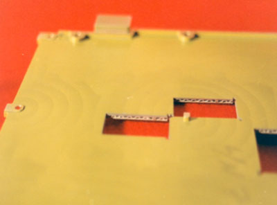
Figure 5: View of Internal Heat Exchanger with sections removed for examination
The Aluminum-Beryllium Alloy F-22 Liquid Flow Through Heat Exchangers underwent qualification testing per the specification and drawings. Piece parts were machined, brazed with internal finstock and then finished machined to final dimensions followed by coating.
After finish machining of the LFT heat exchanger, the rails were electroless nickel plated according to MIL-C-26074 Class 3, Grade A and then over plated with cadmium per QQ-P-416 Type 2, Class 1 with supplementary chromate treatment. The facesheets, where eventually the PWB’s and components would be bonded, were coated with the primer.
Qualification testing included proof pressure testing, pressure cycling, burst testing, and sectioning to examine the braze joints and plating interfaces and thicknesses.
The heat exchangers were visually examined, photographed, x-rayed, and pressured to a proof pressure of 280psi. One was then pressurized up to 1000psi and another was pressure cycled between ambiant and 125psi at a rate of 12 cycles per minute. Both were visually examined after testing, one was subsequently tested for 96 hours in salt fog per ASTM-B-117 (5 % salt fog at 95 ºF) and examined for signs of corrosion. It was then sectioned to determine internal corrosion at the quick disconnect locations. Another was sectioned to characterize the braze joints between the facesheets and fin stock and between the facesheets and rails. The various platings were also evaluated and measured for thickness. The LFT’s passed all examinations and were successfully qualified for use on the F-22.
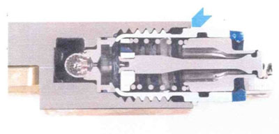
Figure 6: Magnification of 2.5X, cross section of quick disconnect in the LFT