
Figure 1: STS-95 Space Shuttle
The Gas Gap Thermal Switch was a successful assembly designed and fabricated by the Peregrine Falcon Corporation for NASA and flown on the Space Transportation System on board the Space Shuttle Discovery (STS-95).
The Gas Gap Thermal Switch is presented in Figure 2 below. The switch operates by transferring or isolating a thermal load from one end of the switch to the other. A very small gap exists between the two ends. When a gas is present within the gap, thermal energy is transferred and when the gas is evacuated and a vacuum exists, a thermal shunt is created. The alignment of each end is controlled by a precision machined inner sleeve, which keeps the two surfaces aligned and the gap fixed. Exterior to the switch is an outer bellows. This stainless steel outer bellows is electron beam welded to the ends and provides a hermetic seal around the thermal switch while establishing a long, low conductance thermal path to minimize any thermal leakage from one end to the other. The internal cavity created by the bellows produces a leak tight cavity that thermally isolates the conducting parts of the Gas Gap Thermal Switch (GGTS) from the exterior environment and allows control of internal gas pressure. A conducting gas is introduced through a tube at one end of the GGTS. The amount of heat transferred in this GGTS is a function of the gap distance, the gas employed and the gas pressure. The adjustability of this GGTS can come from either of two sources. First, the overall gap distance and second the gas type and pressure. Increasing and decreasing the gap and gas pressure provides a modulation of the thermal transfer through the thermal switch. This GGTS provides control over the operating temperature range of an instrument or electronic device.

Figure 2: Gas Gap Thermal Switch flown on STS-95
The thermal switch can operate from cryogenic to very high temperatures well above 100ºC. In addition, since the gas gap can be evacuated, a vacuum formed between the surfaces can yield a near 100% shunt of the conductive thermal path. Our calculations show that an “On/Off Heat Flow Ratio” value of 100 can be surpassed by this design. The overall structure can be produced in a manner that will yield a GGTS that will operate in both micro g and high g environments.
Background
In the past, typical heat switch transfer devices relied upon paraffin wax in order to switch the devices on and off. The on and off mechanism is basically the pressure developed by the wax as it expanded while heating up in order to move a particular surface into contact of another surface and hold it there in order to create a conductive path to transfer the thermal load. These devices can operate fairly well in atmosphere and non-critical situations. However, the device function to bring two flat or spherical surfaces together is very complex and has performance issues with how much contact area can actually be achieved.
The application for this type “Thermal Switch” is for very temperature sensitive and usually cryo-cooled assemblies, which require very high reliability, like focal plane arrays (FPA’s). In earlier sensor systems, many of these FPA’s were directly connected to a cryo-radiator and passively cooled as active cryo-cooler technology was too immature for use. This passive cooling connection was very reliable and worked well down to a mid-range operating temperature (~150 K). However, the thermal capacity was usually very limited resulting in the need for many high intensity/costly efforts in sensor design and fabrication to drive any parasitic loads around that critical thermal connection down to absolute minimums. It also required precise and continuous attitude control of the spacecraft to prevent the cryo-radiator from being exposed to any high intensity radiation sources (Sun, Earth, Moon, etc.). An efficient thermal switch was desired and needed in these types of systems to limit the heat absorbed by these cryo-radiators as the spacecraft performed its required on-orbit maneuvers or to switch to a second cryo-radiator installed in another part of the spacecraft which may have a better cooling view situation.
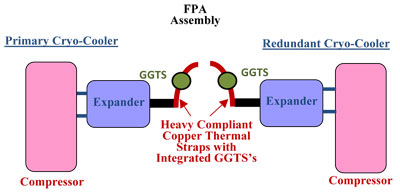
Figure 3: Primary & Redundant Space Cryo-Cooler Arrangements:All Primary & Redundant Cryo-Cooler System Arrangements Need a High Efficiency Thermal Switch to Limit “Off-State” Cryocooler Parasitic Loads
Most recent sensor systems incorporate much higher performance FPA’s that require cooling to operating temperatures well below those earlier passively cooled systems (typically 40 K to 80 K depending on the type of FPA and the operating spectral bands of interest) and modern active space Cryo-coolers are incorporated to achieve these operating temperatures. However, since this cooling function is so mission-critical in these systems, the current need is for an efficiently integrated Primary & Redundant Cryo-cooling System. The Cryo-cooler thermal connection to the FPA assembly it is to cool must be a highly conductive, low loss thermal connection to limit the cooling capacity that the “On State” Cryo-cooler has to satisfy and limit the very high power inputs that must be fed into that cooler. Having an “Off State” Redundant Cryo-cooler with its high thermal mass at space ambient temperatures also connected to the thermal connection creates a very large parasitic leak for the “On-State” Cryo-cooler. High efficiency thermal switches that are integrated into these critical thermal connections allow the parasitic losses to the “Off State” Cryo-cooler to be severely limited yet still allow the Redundant Cryo-cooler to be connected to the FPA and provide the needed cooling. When and if the Primary Cryo-cooler fails or degrades to the point that the Redundant Cooler is activated and the Primary Cooler is de-activated, the thermal switches are rearranged to limit the parasitic losses that the now active redundant cooler must accommodate. This type of Cryo-cooler system also allows space sensor systems to increase their cool down times or the mode transition times (when the new mode requires a lower FPA operating temperature) by activating both Primary and Redundant Coolers together to increase the cooling capacity as needed. However, in addition to having very low loss in the “Off State’, these thermal switches must be very efficient in the “On State” to limit the amount of additional load that is placed on the Cryo-cooler to drive cooling capacity through the switch and they must be very compact and light weight as they will need to be packaged into a very tightly packaged space. Figure 4 below shows an actual picture of a recent space sensor FPA cavity to illustrate how densely packaged these spaces are. Obviously the smaller that the active part of any thermal switch is, the more likely it is to be adopted in these very tight cavity packaging situations.

Figure 4: Picture of Recent Space Sensor FPA Cavity shows how tightly packaged the space around the FPA Assembly is and emphasizes the need that any High Efficient Thermal Switch not only be Highly Efficient; but, also be very Compact and Light Weight
In the space ambient temperature ranges (-60ºC to +100º C) space systems have always had a desire to be able to switch thermal paths to their ambient temperature radiators “on” and “off” to avoid unnecessary solar loading as the spacecraft moves through its orbital path and when on-orbit maneuvers have to be performed to meet mission requirements. Though the need in this area is not as demanding or as urgent as described above, the need is there and will continue to be there. More recently, as programs like the Operationally Responsive Space (ORS) program have moved forward in development, the need for a high efficiency thermal switch in the space ambient temperature ranges has grown. The driver in the ORS case is their very strong requirement to be able to integrate a satellite and launch it in an extremely short period of time. The ORS strategy to meet this requirement is to develop and store very adaptable satellite hardware and assemblies that can be pulled from stores once a mission is initiated, quickly assembled, mated to the selected sensor payload needed for that mission, and then adapted as needed to perform the specific mission required. In regards to the thermal management system, the current thinking within ORS is to manage the thermal loads on the satellite and payload by managing the power and the duty cycles of the equipment onboard so as to avoid exceeding any subsystem or component’s operating temperature range. The use of GGTS’s (as shown in Figure 5) can provide the thermal management needed.
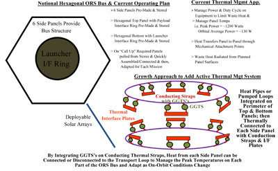
Figure 5: Hexagonal ORS Bus with Active Heat Loops integrated into the Top and Bottom.
By Thermally Connecting each side panel through a set of GGTS’s to these Active Heat Loops, ORS Buses can be Pre-Made and Stored; then, easily and quickly adapted to a variety of ORS Missions. Additionally, real-time On-Orbit Thermal Management can be accomplished by activating, de-activating or adjusting gas pressure in these GGTS’s as conditions / orientations On-Orbit change.