
Figure 1: Advanced thermal control devices for high performance spacecraft applications
The increasing performance of space borne instruments, electronics and communication systems result in the need to dissipate much larger thermal loads while meeting demanding weight and size constraints. In addition, tight temperature control is also required for optical alignment needs, lasers, and detectors. There is a drive for miniaturization with micro electro-mechanical systems which creates an environment demanding an enabling thermal control solution.
Peregrine believes that an innovative and enabling solution is offered by the new technology of pulsating heat pipes, specifically in micro-channel embedded pulsating heat pipes (see Figures 2a and 2b providing a conceptual view of operation). Up until this point in time all pulsating heat pipes have been produced on a laboratory scale from small diameter bent tubing. Peregrine successfully demonstrated the feasibility of embedding pulsating heat pipes within the plane of a sheet. Sixty Micro-channel Embedded Pulsating Heat Pipes (ME-PHPs) of .044” diameter were placed along the center line within panels that are .120” x 6” x 12.” Testing was performed showing significant increases in thermal conductivity.
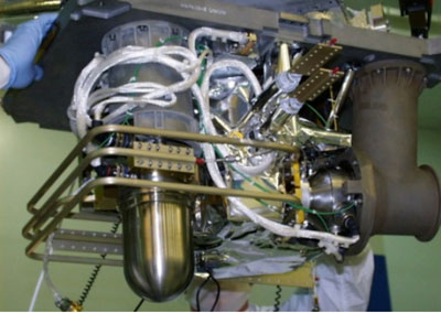
Figure 2: Compact and lightweight thermal control products are required

Figure 2a & 2b: Conceptual sketches of a pulsating heat pipe.
ME-PHPs operate by employing bubble/slug/annular flow of fluid within micro-channels embedded within the plane of a sheet of metal. In order to incorporate the micro channels, two flat sheets are prepared with matching patterns of the micro-channels. These sheets are diffusion bonded together to form a monolithic component with integral coolant passages. The ME-PHP is then charged with a partial amount of working fluid and sealed under vacuum. When a thermal load is applied to the evaporator portion of the ME-PHP the working fluid takes the thermal energy via vapor and transports it via bubble/slug/annular flow. Through a combination of vaporization and sensible flow, energy is transferred to the condenser where the vapor is reduced. The expansion of vapor at the evaporator and its contraction at the condenser along with system perturbations as a result of turns and surface tension within the channels produces a pulsing action that in turn creates a self-contained thermal transport system.
Peregrine embeds pulsating heat pipes within the plane of flat sheets/plates by using printed circuit board technology to micro-machine the channels. Our proprietary diffusion bonding technology is then applied to assemble the ME-PHPs. Each of these processes has proven feasibility and used together can readily produce ME-PHP’s. Printed Circuit Board Fabrication (Photoetching) is a process where a metal is etched with very fine detail. This process is readily available and well characterized. It starts with a piece of sheet metal or foil and then a photoresist is applied. Artwork, which appears as a photographic negative, is indexed to the prepared metal and they are placed into a high intensity light bench. Essentially, this process develops the artwork selectively onto the photoresist creating a chemical resistant mask that rigidly attaches to the metal protecting it in some areas and leaving it exposed in others. Chemical etching of the unprotected metal follows. This process allows you to etch through parts or just partially through allowing one the ability to create through holes and channels where desired and in any shape that can be drawn. The key advantages of printed circuit board fabrication is that it is readily available, has a long history and the process is fully characterized. The process can easily produce large panels in the 18” x 36” size and is easily scaled up from there. Also very detailed channels, as small as .005” can be obtained up to over .250.” Any basic shape can be etched into the sheets such as, serpentine channels, wavy patterns, tapered channels, straight channels, and other very detailed shapes. Different patterns or slight modifications on the same sheet can also be applied to influence the thermal conductance path. Multiple ME-PHPs can also be etched into the same panel in a side-by-side, end to end or even in oblige patterns.
In its simplest concept, diffusion bonding is the bringing together of metal detail parts under temperature and pressure to allow for grain growth across the interface boundary. In combination with Photo etching, it can create a stack up of multiple layers with integral micro-channels. The ME-PHPs can be placed one on top of another with almost endless possibilities. The as-diffusion bonded stack up will appear in cross section as a monolithic block with integral flow passages. Any thermal impedance due to the metal joining uncertainty is eliminated. Many types of materials can be diffusion bonded including: Copper, Inconel, Stainless Steel, Titanium, Nickel, Silver and others. Another key advantage to this process is that it is step-able. Subassemblies can be diffusion bonded and qualified and then those subassemblies can be diffusion bonded together making even a more robust process/assembly.
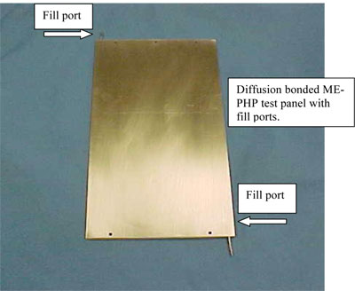
Figure 3: An Assembled Micro-channel Pulsating Heat Pipe
The testing of the ME-PHP panels was performed by applying resistive heaters to one end of the ME-PHP test panel while fixing the other end to a heat sink. Thermal couples were attached to the surface of the test panel approximately .05 meters apart in line with the thermal path. Multi-layer insulation was placed around the panel and then a metal bell jar enclosed the set-up to establish a vacuum environment for testing. Testing verified significant thermal conductivity results. Peregrine predicts up to a magnitude thermal performance increaser over simple conduction.
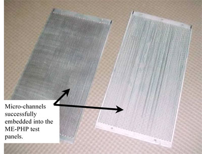
Figure 4: Top and matching bottom Micro-channel Pulsating Heat Pipe (ME-PHP) Assembly
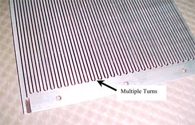
Figure 5: Close up of one side of a Micro-channel Pulsating Heat Pipe (ME-PHP) Assembly