
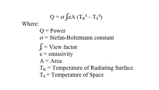
Figure 1: Thermal control device for a military satellite
Peregrine, in collaboration with its Aerospace customer, undertook a design, manufacture and testing contract to produce a set of shunt resistor bank heater plates for a satellite application. Specific to this application, is the requirement to dissipate 900 Watts of thermal energy into space. Due to the environment of space, this thermal load had to be transferred by radiation into space.
A morphological chart along with a Statement of Work was created between Peregrine and the customer for the design, manufacture and testing of these heater plates. Specifically voltages and amperage, along with envelope constraints were identified and parameters were established. Beginning from that point, Peregrine set off to establish a design that would allow the dissipation of the thermal energy and the creation of the overall model. Due to the constraints on volume, footprint and weight for satellite applications, Peregrine optimized the design to as small a footprint as possible. This was done by creating a set of serpentine cable heaters to be metallurgically joined to a carrier plate. In addition, an advanced thermal coating was applied in order to optimize emittance of thermal energy into space. The general radiation equation between two surfaces is typically derived as follows:
Based upon the above equation, Peregrine determined that four heater plates with a surface area of approximately 50 in2 each would be necessary in order to dissipate the 900 Watts of thermal energy. Peregrine modeled, analyzed and produced initial SRB plates in order to validate the design. Through the course of manufacturing, the cable heaters had to be precision formed, metallurgical joined to the carrier plate, and then the emittance surface was coated with thermal coating in order to achieve its proper finish. The cable heaters were terminated along one edge of the heater plate. At this location, lead wires were attached, the cable heater ends were glassed in order to seal against moisture contamination, housing was added and the final overall contact area was potted for strain relief. Each set of heater wires within the cable heater located on the SRB plate was electrically isolated from the plate. Each plate had the potential of dissipating 225 Watts of thermal energy. A bank of four plates equated to the 900 Watt goal.
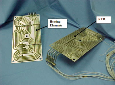
Figure 2: Shunt Resister Bank Heater Plate
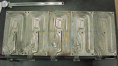
Figure 3: Fabricated Heater Plates in Process
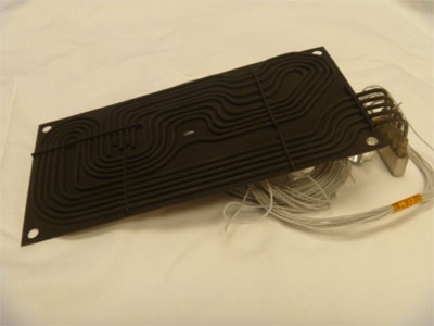
Figure 4: SRB Heater Plate with Thermal Coating for High Emittance