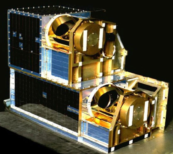
Figure 1: AMSU-A
Our people assisted with the Advanced Microwave Sounding Units (AMSU-A & B) space flight instruments, which were multi-channel passive microwave radiometers that measured global atmospheric temperature profiles from the advanced TIROS-N spacecraft. Aerojet Electronic Systems (now Northrop Grumman) was responsible for the delivery of the AMSU-A to NASA / NOAA. The AMSU-A system provides information on atmospheric water in all of its forms with the exception of small ice particles, which were deemed transparent at microwave frequencies when this design was produced.
Under AMSU, the radiometric characteristics of the atmosphere were determined primarily by the absorption and emission characteristics of the oxygen molecule in the 50-60 GHz band of the frequency spectrum. Since the mixing ratio of oxygen is constant in the atmosphere, the contribution of a particular layer of the atmosphere to the total radiation detected by a space borne radiometer operating in this frequency range is primarily controlled by the air temperature and the product of two competing factors. The factors are the emission per unit volume; which decreases monotonically with height due to the decreasing air density; and the transmission factor of the atmosphere above the layer under consideration. The resultant product is a function which typically peaks at some height and decreases with distance away from the peaking altitude. By selecting frequencies with different absorption coefficients, weighting functions emphasizing radiances from preselected atmospheric layers may be obtained. The problem of profiling the temperature of the atmosphere then reduces to finding the most probable profile which, when weighted by the appropriate weighting functions, produces the measured brightness temperature values of the selected frequencies.
The AMSU-A sensor is a millimeter wave instrument, which passively monitors the radiation from the earth’s surface and atmosphere in the microwave portion of the spectrum. The AMSU-A was made up of two modules A1 and A2. Each was configured in the same fashion and consists of four major sub-assemblies:
1. Antenna /Drive/ Calibration Sub Assembly
2. Electronics Sub Assembly
3. Mechanical Structural Sub Assembly
4. Thermal Sub Assembly
In each module A1 and A2, the basic design of the sub-assemblies was the same differing only as a result of the specific frequencies. The total instrument was a 15-channel instrument. In one module, 13 channels exist; this was identified as AMSU-A1. These 13 channels measure higher frequency O2. Two separate and independent antenna/drive calibration sub-assemblies and electronic sub-assemblies are integrated with a single common mechanical structural sub assembly and thermal sub assembly. The AMSU-A2 module was a 2-channel module. These are low frequency H2O channels.
The cross track scanning of the earth scene was accomplished in a stepped fashion with a 165 millisecond at each of the 30 earth viewing angles, and a 384 millisecond at the cold and warm calibration angles. Stepping of the antenna between the last earth viewing position and the cold calibration position, the two calibration positions and the warm calibration position in the first earth viewing angle was accomplished in a rapid step fashion. A complete rotation of the antenna was accomplished in 8 seconds. During each rotation of the antenna, AMSU-A modules are calibrated with a cold reference by review of the cosmic background and a warm reference by review of an ambient RF target at a nominal 300ºK temperature.
Our people helped design and produce the parabolic reflectors (A1 Antenna) for the AMSU-A instrument. These parabolic reflectors were fabricated from detailed components of beryllium, brazed together in order to create the overall antenna. One of the key components was the parabolic reflector, which captured microwave energy and transferred it to the detector within the instrument. This was a precision creep formed surface, gold plated and metallurgically joined to the rest of the shrouding and shaft that kept the alignment of this antenna to successfully create the overall instrument. This can be seen in Figure 3, a companion instrument was also produced using the same technique. The other shroud was fabricated of beryllium and then coated with a mylar film to meet emissivity and absorptivity requirements. These precision antennae were an enabling factor in the overall instrument since the weight; moment of inertia and stiffness of these particular components were fabricated from beryllium, which allowed for smaller motors and encoders to be used. This allowed the overall program to hit its weight and performance targets.
These antennae are currently flying on the TIROS-N weather satellites and are successfully providing meteorologists the information necessary to predict weather and weather patterns on the earth.
Block Diagram
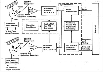
Figure 2: A block diagram illustrating the layout of the two A1 & A2 modules
Peregrine is a specialty design, fabrication and test company specializing in spacecraft and R&D components. We primarily rely on SolidWorks as our modeling software and for its simulation capabilities. Peregrine has produced many spaceborne and R&D assemblies and have been responsible for not only fabrication; but for the design, simulation, fabrication and qualification of those components. Peregrine supports many commercial, NASA, NOAA and military satellite programs.
Peregrine’s personnel were involved in the AMSU –A project in support of Aerojet Electronic Systems. In addition, British Aerospace produced a complimentary AMSU-B instrument for EUMETSAT. Peregrine’s people were an important part in producing these two instruments.
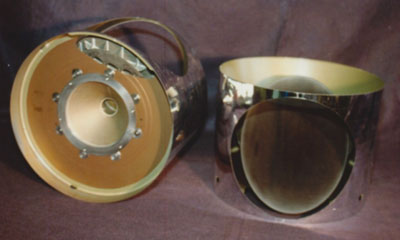
Figure 3: AMSU-B Hardware designed and fabricated