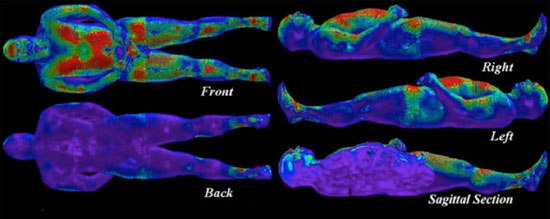
Figure 1: Heat exchanger to lower and manage body temperature
At times, under certain medical conditions, it is important to control the overall temperature of the body. By lowering the temperature, there are certain medical advantages in order to slow down the recovery rate or response rate from a patient. This is done by inserting a catheter within the central venous system of the patient and then running cooled saline through the catheter. Usually, the saline does not enter the body, it is just used as a cooling fluid and the patient is cooled or warmed as the venous blood passes over the catheter. Due to the potential proximity of the catheter to vital organs like the heart, it is essential to have a low resistive leakage (electrical current) transferred from the catheter to the patient. Peregrine was asked to design a heat exchanger that allowed for 400 Watts of cooling capability and a resistive leakage (or capacitance reactance) of less than 50 micro amps.
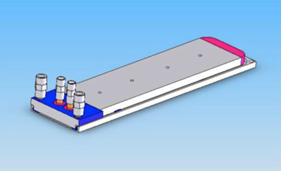
Figure 2: Heat Exchanger
The design of this heat exchanger had to be balanced between the need for electrical isolation and the need for thermal transfer. The fundamental criterion driving the success of the heat exchanger is the surface area. Surface area directly affects capacitance and in turn, resistance leakage. The smaller the area, the smaller the capacitance. Area also directly affects heat transfer- the larger the area, the more heat transfer. These two key parameters are diametrically opposed.
The basic design concept was to separate the coolant loop; one that would cool the saline solution (PGW) and one that would be a refrigerant loop to cool the PGW loop. This is shown in Figure 3.
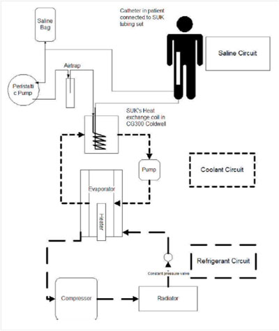
Figure 3: Schematic
Separating the one coolant loop from the other is a dielectric material that will allow us to meet the resistance leakage requirement while also transferring the thermal energy desired. Peregrine blended a dielectric material, which is an insulating material. The dielectric of any capacitor will conduct some very small amount of current. Thus the charge of a capacitor will eventually “leak off.” Some types of capacitors have higher leakages than others.
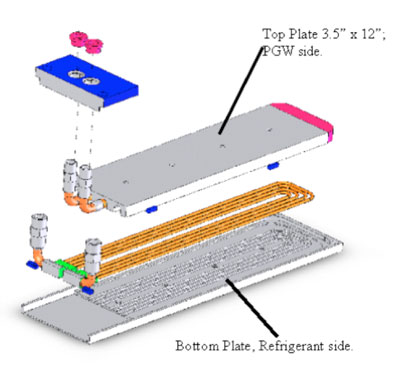
Figure 4: Heat Exchanger Concept.
In an electrical schematic a capacitor “C” is usually shown as below in Figure 5. But all capacitors have resistance leakage around them as accurately depicted in the Figure 6 below. Limiting this leakage resistance is key to the design. The parallel resistor represents the extremely high resistance of the dielectric material through which there is a leakage current.
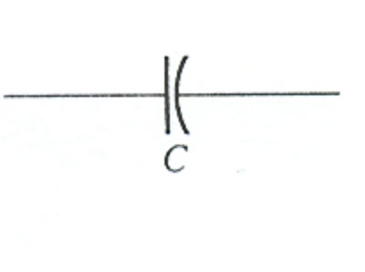
Figure 5: Capacitance as Typically Illustrated
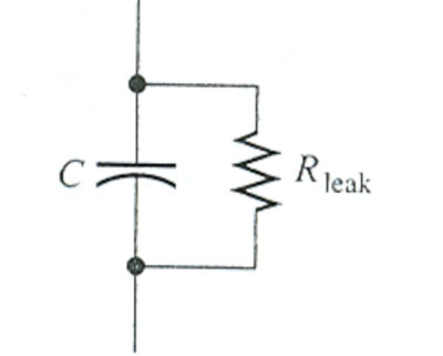
Figure 6: Correctly Illustrated
There is a direct relationship between the dielectric strength of the insulating material and the level of leakage; the higher the dielectric strength, the higher the resistance and in turn the lower the resistive leakage current. In contrast, thermal conductivity typically is the inverse of what is required to achieve a low resistive leakage. The higher insulating properties of the material, and the thicker it gets, the less heat transfer occurs.
Peregrine worked with the customer on this particular critical application to formulate a statement of work along with a valid morphological chart in order to establish the parameters of the design.
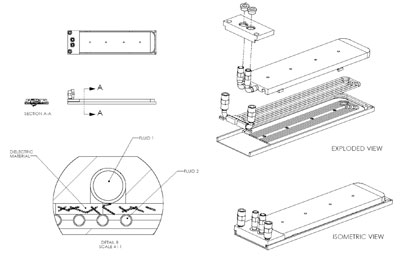
Figure 7: Views of Heat Exchanger
Peregrine was successful in developing a design, building prototypes and validating the design for production. This design yielded a 42 square inch heat exchanger with a capacitance reactance of 6 M ohms at 50 hertz while providing a small thermal barrier between the two heat exchanging surfaces with a temperature drop of only 2.6°C. This heat exchanger was the solution to our customer’s prescribed problem.